
In 2017 Viianki, a demo by The Not Yet Rusty Collective, made an impression on me. Its coder and my good friend msqrt had implemented very good looking stochastic transparency for foliage. The hand drawn sprites communicated a real sense of depth and that's when I realized how much the impression of a dense woods is created by the parallax you get when moving your head.
Now in 2021 I finally made my own experiments using a similar technique. Instead of stochastic rasterization I continued with the point based technique of Eternal Fortress. Our new demo A New World Awaits (video on YouTube) has more connections to Viianki still: I used msqrt's OpenGL base code and the music was made by shaiggon who also scored Viianki. But enough with history, what's new about this years demo?
Let's begin with a feature listing:
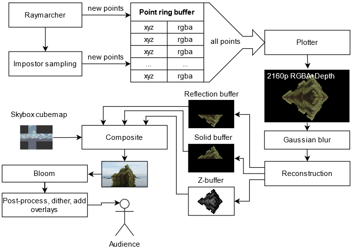
The high-level flow of the renderer.
| Pass | Rendering time |
| Raymarching | 25 ms |
| Plotting | 18 ms |
| Postprocess (all) | 8 ms |
| Postprocess (two-pass blur only) | 2 ms |
| Total | 51 ms |
Measured on a GTX 1060 6GB in the opening shot. The RTX 3070 that was in the compo machine is exactly 2.5 times the speed of a 1060.
I still use the same hierarchical raymarcher I wrote about earlier. I tried to get rid of it but it was still 10% faster than a simpler two-level hierarchy (16×16 tiles) of Psycho's approach used in One Of Those Days. The fractals shown in the demo are the Mandelbox (GLSL distance function by Řrřola), BioCube (by DarkBeam) and a 3D Kleinian fractal (by Knighty).
Raymarching is not done at native 1080p but at 1440×810 instead. To be honest, I was planning to bump this up for the release but I forgot.
Nothing fancy here. The raymarcher casts a single shadow ray towards the sun, reads sky irradiance from a 643 cubemap. The plotting pass applies specular shading with a GGX lobe. Diffuse shading is saved in the ring buffer (it's baked in point color) and reused across frames but specular shading is recomputed for every point, every frame.
Here plotting means writing single pixels without anti-aliasing and splatting means drawing larger anti-aliased discs whose size is usually set in world-space coordinates. You can read more about this in the slides Point-Based Rendering (Matthias Zwicker).
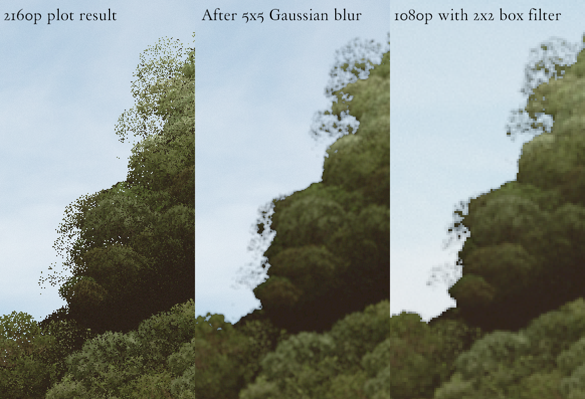
Reconstruction filtering. Left: The raw 4K plotting result. Middle: a two-pass Gaussian blur smooths the image. Right: Downsampling to the final 1080p resolution with a 2×2 box filter. Edge detection is also performed here to bias alpha of interior pixels to avoid outlier holes.
In Eternal Fortress each point was rendered using a box filter and weighted transparency. So each point had to write into four pixels in the final frame buffer. It was a scatter operation. In the new demo I ended up using a gather approach: all points write their color to a single pixel in a 3840×2160 framebuffer but the picture is blurred afterwards (see the middle pane in the picture above). The result is the same but it's easier to make the points appear larger by increasing the blur radius. So in a sense the plots are extended into circular splats of uniform size.
In terms of code, this is what the plotting shader does:
// The "sampleBuffer" has a single unsigned 64-bit int per pixel (at 2160p rez).
layout(std430) buffer sampleBuffer {
    uint64_t depthColorSamples[];
};

// Pack a RGBA and a linear float z into a single 64-bit uint with this layout:
//
//  value    ZZZZZZZZ AABBGGRR
//  bit      63       31     0
//
// Note that "packUint2x32" puts the first argument in the least significant bits.
uint64_t depthColor64 = packUint2x32(uvec2(packUnorm4x8(color), floatBitsToUint(z)));

// We can do a Z-test with a single atomicMin since
//  (a) a non-negative float will sort correctly when reinterpreted as an uint32
//  (b) Z values in the most significant bits make sure only Z and not color will
//      matter in the comparison done by atomicMin.

atomicMin(depthColorSamples[pointIndex], depthColor64);
If you want to learn more about this, consider checking out Rendering Point Clouds with Compute Shaders (Markus Schütz) and Stochastic Transparency (Enderton et al.).
The 2160p frame buffer where points are plotted is stored in a 32×32 tiled format. This improved the plotting speed 20-30% when compared to a linear storage order. You can read more about this technique in ryg's 2011 blog post Texture tiling and swizzling.
For example the memory storage order of a tiled 4×4 framebuffer with 2×2 tiles would look like this:
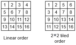
The mapping is pretty easy to do, you find out which block the coordinate is in (bx and by) and its offset inside the block (lx and ly) and then compute the final index based on those.
// Maps a pixel coordinate "c" and the framebuffer size into an array index.
int coordinateToTiledIndex(ivec2 c, ivec2 size) {
    const int SIZE = 32;
    const int SHIFT = 5; // findMSB(SIZE);
    const int MASK = SIZE - 1;
    const int B2 = (1 << SHIFT) << SHIFT;
    const int bw = size.x >> SHIFT;
    int bx = c.x >> SHIFT;  // which block the pixel is in
    int by = c.y >> SHIFT;
    int lx = c.x & MASK;    // pixels offset inside the block
    int ly = c.y & MASK;
    return by*B2*bw + bx*B2 + ly*SIZE + lx;
}
Since we are plotting points anyway it was simple to add motion blur right there instead of doing it as a post process effect. Each point's projected coordinate is interpolated between past and future camera positions based on per-pixel noise.
![Two projected point positions are linearly interpolated using a noise factor t \in [0,1] to get the final plot position (purple).](new_world_img/motion_blur_interpolation.png)
Two projected point positions are linearly interpolated using a noise factor t ∈ [0, 1] to get the final plot position (purple).
The good thing is that it's practically free (and keeps raymarching coherent) but the downside is that some surfaces become transparent because the points get smeared across the screen. It also made water reflections pretty annoying to code because now there wasn't a single true camera projection to use to raytrace the water plane.
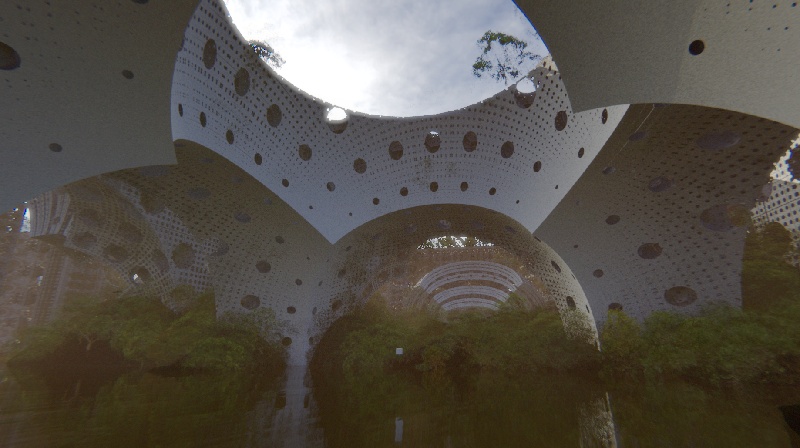
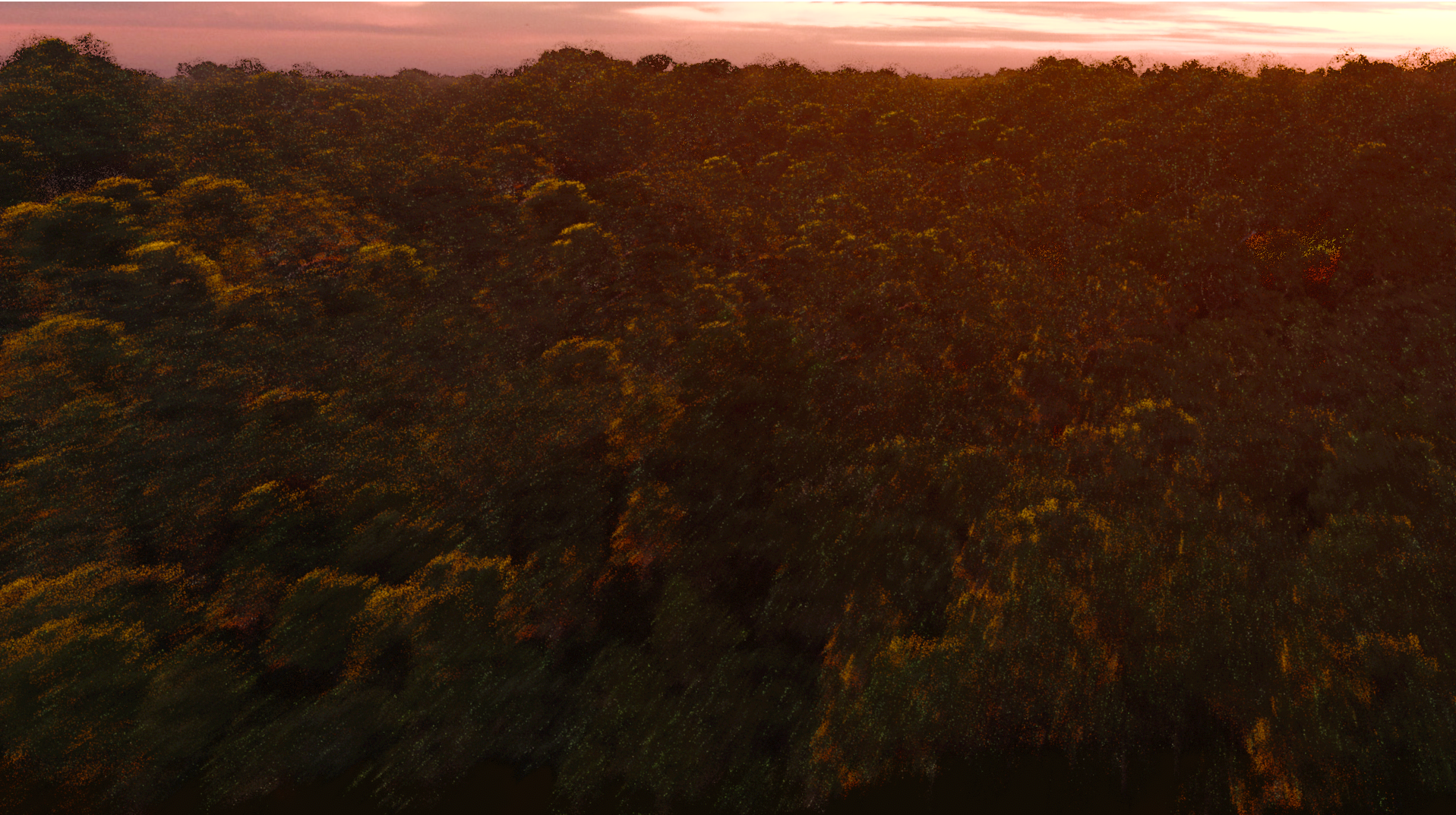
The foliage is correctly sorted and blends with rest of the geometry. A brightened up shot from the demo.
Foliage is rendered as points just like the solid geometry. Their points are added to the same big ring buffer so transparency and Z-test work automatically. This gives the happy little trees a really soft and fluffy look that's hard to replicate with just polygons. This worked out really well in the end.
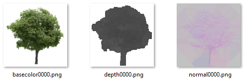
I rendered some free tree models into color, depth, and normal textures with Blender. The raymarcher then spawns the foliage points based on ray intersection positions and samples the 128×128 textures to give the points their final color, world space normal and an extruded position based on the depth map.
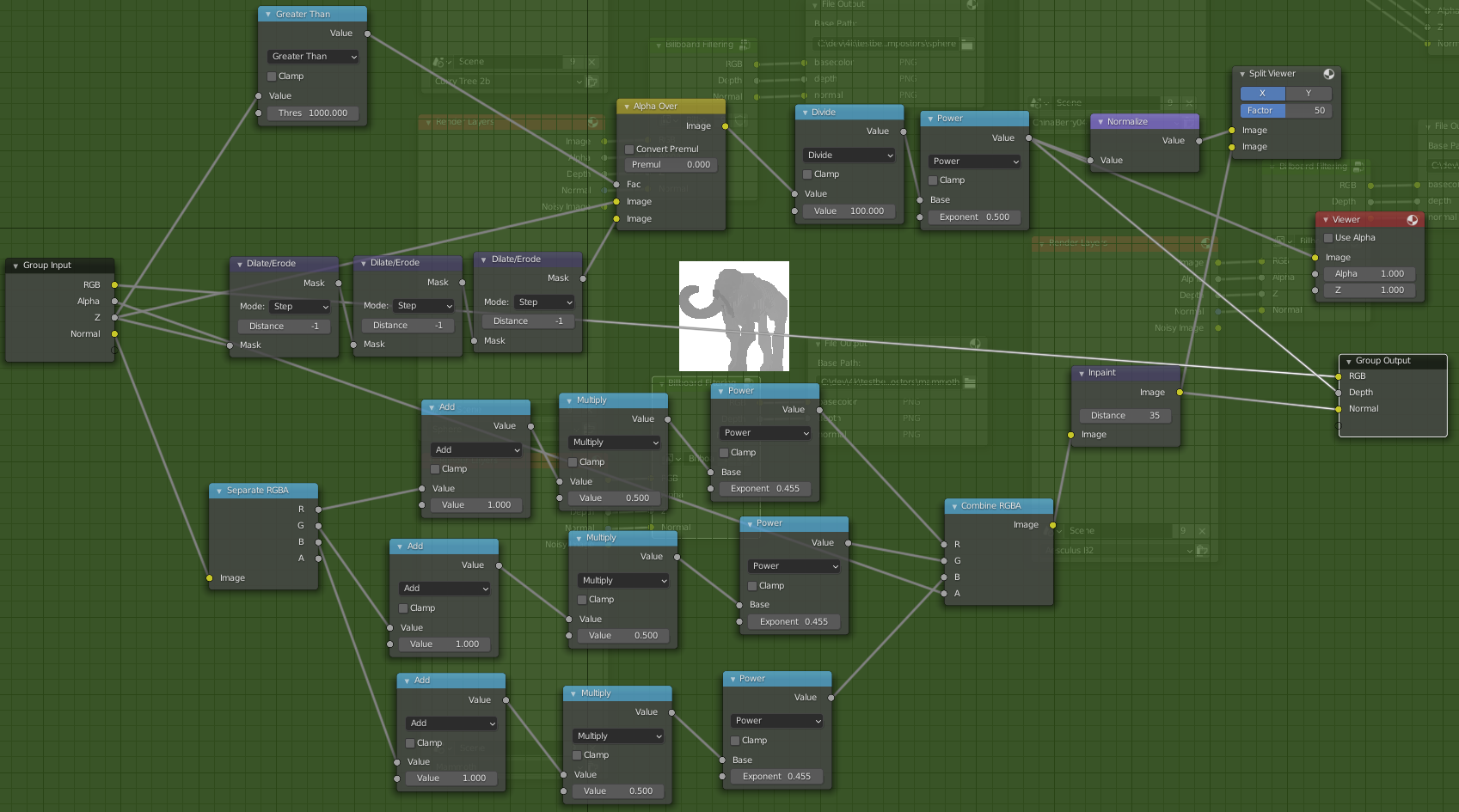
A Blender compositor graph that packs the three textures.
Tree points are spawned by the raymarcher. The shader has a function void addPoint(vec3 worldpos, vec4 color) that can spawn a point anywhere, so in addition to adding a point to represent the hard surface a ray hit, the shader can also add other points in its vicinity. In this case they represent foliage.
After each raymarch intersection the marcher computes a hash of its rounded location, giving a 3D tile index. It then samples a randomly selected impostor image and spawns a new point based on the rounded location and the impostor color, normal, and depth. Multiple pixels will get the same tile index so each tree will get points roughly according to its screen space size. Each tree has a random offset inside its cell to break up the grid.
It's hard to explain but the below image shows how the 3D tile indices look.
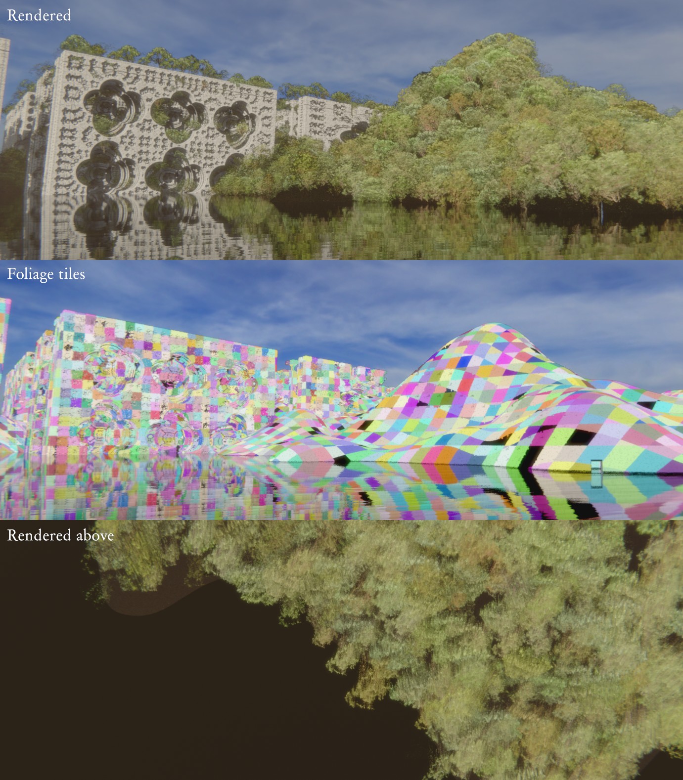
Foliage tiles. Top: The final rendered image. Middle: the unique hashed tiles for each pixel. Bottom: The same shoreline but with the camera pointing down. Notice the shape of the impostors given by their depth maps.
For each tile that gets a tree, a plane is rejection sampled like shown below.
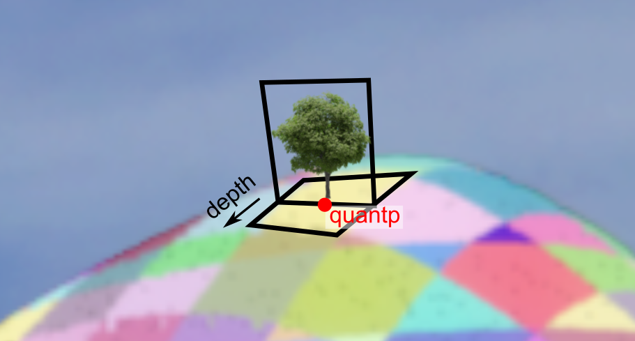
An example impostor. Each ray that hits the yellow ground rectangle will pick a random texture coordinate on the upright plane and read the color texture's alpha channel at that location. If alpha is greater than zero then depth and normal map are read too and a new point gets added. The point is moved along the "depth" arrow direction accordingly to give the impostor its 3D shape.
In the best demoscene tradition this approach barely works :) The trees will appear and disappear when you move the camera so everything needs to be tweaked carefully to avoid worst pop in effects. Still, this was excellent workflow wise because everything is done in a single hot-reloaded shader. It also helps that the points are spawned in advance along the deterministic camera paths.
A simplified version of the "spawn rainforest" shader code goes like this:
float voxelDensity = 8; // smaller values produce larger tiles

ivec3 quant = ivec3(p * voxelDensity);               // tile's integer coordinate
vec3 quantp = vec3(quant + vec3(.5)) / voxelDensity; // tile center

// sample a 2D noise for this tile
float density = fbm(quant + ivec3(-99, 31, 44));

// if the noise was large enough, this tile has a tree
if (density > 0.2) {
    // hash the quantized index to produce per-tree constants
    uint quanth = hash(uvec3(quant));
    vec4 uniq = unpackUnorm4x8(quanth); // four unique [0,1] values for this tree

    // pick a random index of the impostor texture
    int ID = int(uniq.x * IMPOSTOR_COUNT);
    float size = impostorSizes[ID];

    // compute a tangent frame for this tree. each impostor tree is basically
    // a plane oriented towards the camera that gets extruded along its depth axis.

    vec3 normal = getOrientedNormal(quantp, surf.normal, voxelDensity);
    vec3 tangent_x, tangent_y;
    makeOrthoFrame(normal, tangent_x, tangent_y);

    // the tile centroid may be above the surface so do a couple of sphere tracing
    // steps using the normal direction
    vec3 vo = snapPointToSurface(quantp, normal);

    // random samples a point of impostor "ID" at point "vo" with its direction
    // given by the three basis vectors and calls addPoint()
    spawnImpostor(ID, vo, basisx, basisy, basisz);
}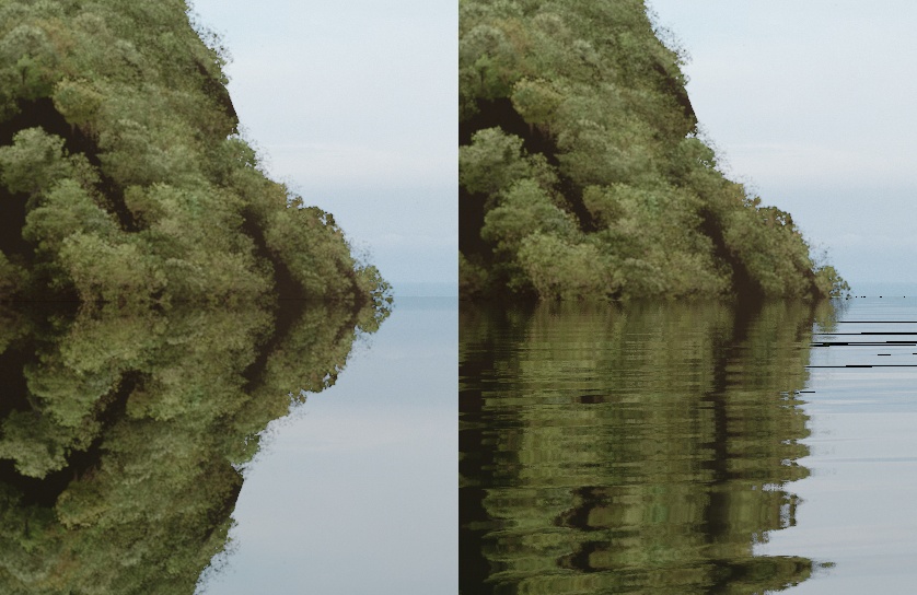
Basic but pretty reflections. Left: the planar reflection without any distortion. Right: after eight texture reads (for blur) using a warped normal. The black artefacts aren't that visible after the post process passes.
It's pretty easy to create reflective water in a raymarcher because you can change ray's direction once it hits the water surface. The problem in this demo is that the hierarchical raymarcher needs the rays to stay on their original course because otherwise the hierarchical acceleration wouldn't work. Tree rendering is another reason; they are not raymarched so they'd need another solution anyway.
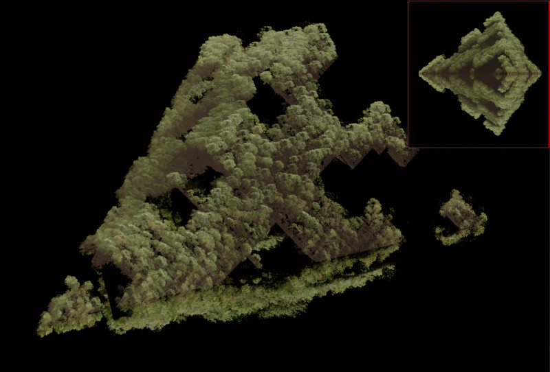
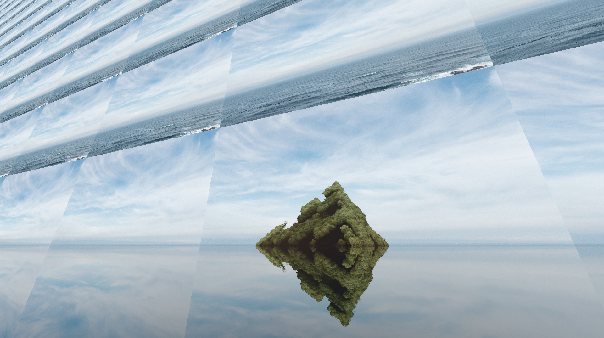
An island with mirrored geometry. The top and bottom halves are raymarched at the same time but bottom one is saved into its own buffer in the reconstruction pass. Inset: The camera's point of view. Note how occluded parts didn't generate any points.
How it works here is a bit of a hack:
This was a real pain to get working with the motion blur and you can still see some artefacts in the final demo. Note that there is no refraction and instead of underwater geometry there's just a solid color. This looked great in my opinion :)
So we have a perfect planar reflection in a texture. How do we need to warp the UV coordinates to make it look like water? I suppose this is something that everyone else knows already but it took me some digging in ancient GameDev.net forum threads to learn.

A simple method I used in the end was to intersect a ray with the water surface, nudge the intersection point along a distorted reflection direction R by a small amount and then project it back to screen space (point B in the diagram). This is the texture coordinate for the planar reflection texture. A variation of this technique is to intersect R with a plane that floats slightly above water and project that point instead.
I wanted a found footage kind of look so I used simple motion capture to achieve that. I used my phone to record some videos where I shake the camera pretending to walk and then used Blender's motion tracking feature to export the tracked point positions to a file. I then ran a Python script that solved a list of (yawdelta, pitchdelta, roll) tuples that the demo loads, interpolates, loops, and applies to the camera direction.
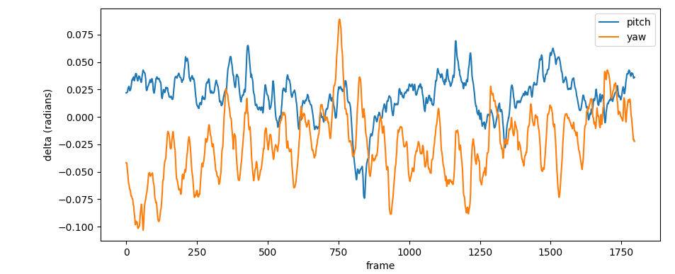
A graph of the "slowwalk" walking animation's X (yaw) and Y (pitch) deltas. In the demo these rotation offsets were amplified.
Looking at it now, it seems like the roll values (not shown in the graph) produced by the solver may have been garbage. It looked OK anyway because most of the motion is from the translation component.
Note that you can also do full structure from motion in Blender and solve for real 3D camera paths. It's a lot of work though and I didn't need it here.
This is not about rendering but I wanted to say a few words about animations. The demo was animated via two text files: the first tells the order in which show each camera pose ("shots.txt") and the other has shader uniform values for each camera pose ("props.txt"). Those uniforms are interpolated between key frames with the smoothstep function.
So let's say we have a demo with two scenes overview1 and overview2 that we wish to show 10 seconds each.
# shots.txt
# start time (seconds)  pose name
0.                      overview1
10.                     overview2
We can then add a two second fade to both of them in by animating the post_gain uniform like this:
# props.txt
#     property  time    value
animf post_gain 0.0     0.0
animf post_gain 2.0     1.0

# "cam" associates the above uniforms to the given pose name
cam   overview1
cam   overview2
Basic stuff. The cool thing is you can "push" and "pop" uniform value sets on and off a stack to build variations of a shot using inheritance. For example to have the same fade in effect but different bloom strengths for the two camera poses, this is how you'd do it:
# props.txt
animf post_gain      0.0 0.0
animf post_gain      2.0 1.0

push
animf bloom_strength 0.0 0.5
cam   overview1
pop

push
animf bloom_strength 0.0 0.2
cam   overview2
pop
Yeah kinda unwieldy, I know, but it worked OK.
Despite being quite slow and surprisingly difficult to download, Nvidia's NSight debugging tool can give you some detailed numbers of OpenGL code. You can't profile your code on the shader level like in DirectX but you can view performance counters for a whole frame and for each draw call:
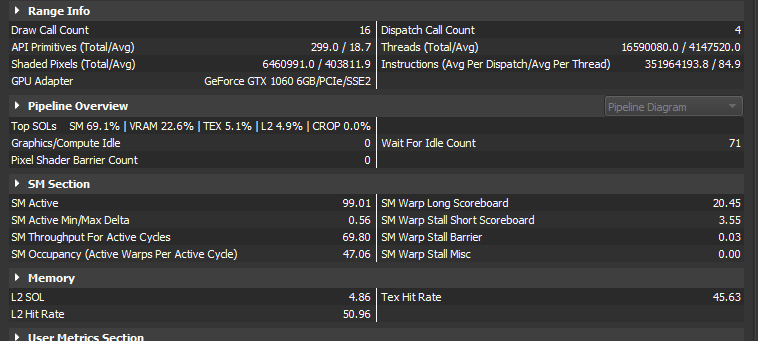
Per-frame statistics.
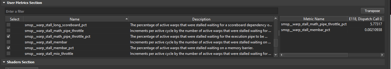
Performance counters for a single compute dispatch.
See The Peak-Performance-Percentage Analysis Method for Optimizing Any GPU Workload on how to interpret these numbers.
I had such a bad time working on the planar reflections (especially with motion blur) that I might stick to screen space techniques in the future. Another thing: noise can look really good if applied at high resolution and blurred & downsampled afterwards. Third thing: where there are Euler angles, there's a gimbal lock. It really bit me with cameras this time.
Also, for some reason there were many comments on skyboxes. Maybe it's because there wasn't a "hero" character to focus on and the sky is very visible in zoomed in shots? Some of them were "matte paintings" btw.
Finally, if you're interested in demo or graphics coding and all this appeared intimidating to you, don't worry. Many complex looking things are very basic once you understand them. Often it's just about having the right Can-Do Attitude and a lot of time at your disposal! That's why I'd like to end this essay with a classic quote from Ira Glass:
Nobody tells this to people who are beginners, I wish someone told me. All of us who do creative work, we get into it because we have good taste. But there is this gap. For the first couple years you make stuff, it’s just not that good. It’s trying to be good, it has potential, but it’s not. But your taste, the thing that got you into the game, is still killer. And your taste is why your work disappoints you. A lot of people never get past this phase, they quit. Most people I know who do interesting, creative work went through years of this. We know our work doesn’t have this special thing that we want it to have. We all go through this. And if you are just starting out or you are still in this phase, you gotta know its normal and the most important thing you can do is do a lot of work. Put yourself on a deadline so that every week you will finish one story. It is only by going through a volume of work that you will close that gap, and your work will be as good as your ambitions. And I took longer to figure out how to do this than anyone I’ve ever met. It’s gonna take awhile. It’s normal to take awhile. You’ve just gotta fight your way through.
Thanks to noby, Trilkk, mankeli, msqrt, and branch for help in editing this write-up.