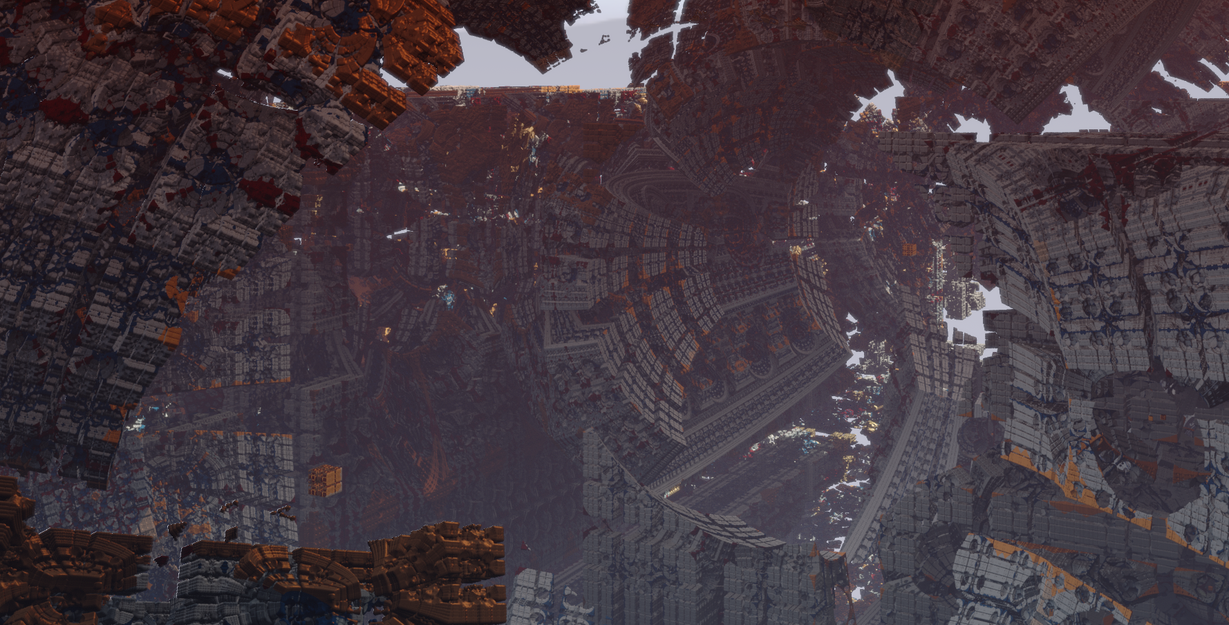
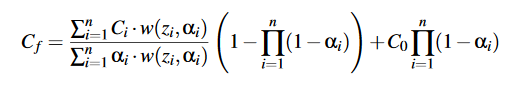
Eternal Fortress (pouet, zip, source) is demo by Peisik for Revision Online 2020. It was born out of desire to show the Mandelbox fractal as a massive sprawling structure it is. This page is a rambling dump of technical thoughts on its rendering techniques.
A big problem with the Mandelbox is that it's heavy to raymarch on long view distances. This makes it pretty much impossible to shoot more than one ray per pixel at realtime framerates, so the image will appear noisy. We know the fractal is completely static, so it should be possible to reuse raymarching results across different frames. How do we store the results across frames?
In the demo everything is actually a point cloud. You can think of it as a particle system where each particle is completely static and lives for 10 frames or longer. The cool thing about this is that even if you can afford only one ray per pixel every frame, you can still keep the resulting point for later frames. So it's a variation of temporal super sampling, if you will.
We store 20 million points in a big fat ring buffer, and on each frame we add about two million (1920 × 1080, one ray per pixel) new ones to it, dropping out the oldest points.
The overall pipeline is the following.
Every point contributes to some per-pixel weighted average color using a variation of Weighted Blended Order-Independent Transparency (blog post) by Morgan McGuire and Louis Bavoil. The idea is to give closer points more weight than those far away from the camera, so in the end a weighted average will give proper occlusion. Accumulation is done via integer atomics. My code didn't support proper per-point alphas though, see the latter part of this page for caveats.
The downside of this approach is that splatting points can get very expensive. For example, specular shading needs to be done 10x per pixel every frame. There are also six 32-bit atomic writes for each visible point to actually draw it.
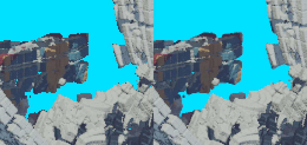
Now we have temporal super sampling but when the camera moves we get artifacts on screen boundaries:
When the camera is moving left, the screen boundary doesn't get enough samples and becomes noisy.
This happens because newly disoccluded surfaces have been hit by only a few rays. So how do we get more samples where we need them?
I knew the demo would have deterministic camera paths so I came up with a way to easily sample future frames. Instead of shooting rays for the current frame n, shoot them for the camera pose of n + 1, and store the resulting world space points in the ring buffer introduced above. Again, on each frame we splat the whole ring buffer on screen with a compute shader. This is illustrated in the diagram below.
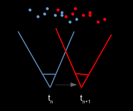
While we are splatting the points from the camera pose at tn we have already generated points tn + 1 well in advance. This way point generation gets amortized over time without artifacts of traditional temporal supersampling techniques.
In the demo each frame produces roughly one point per pixel, so ~2 M for 1080p, and the ring buffer has space for 10x that. In the demo, future points are generated actually four frames in advance. This even works over camera cuts.
The ring buffer stores points as 32-byte structs.
struct RgbPoint {
    vec3 xyz;               // world-space coordinate
    uint normalSpecularSun; // packed normal and material
    vec3 rgba;              // diffuse color
    float sec;              // which scene spawned this point
};
The last member sec is a hack to remove unused points on scene cuts. This struct could've been packed much tighter.
Reconstruction filter. The splatting pass could draw the points as just single pixels but that way you end up amplifying some of the geometric aliasing. Some people prefer that "sharp" look but here the idea was to a high quality picture.
Point reconstruction filter. Left: with 1 pixel splats (box filter), right: 2x2 tent filter
I'm not sure if the final reconsturction filter even qualifies as a tent filter (it's basically an inverted bilinear tap) but as you can see it already looks much better so I left it alone.
Z-weighted average. Each point is given a weight and the sum of all weights are accumulated to a separate buffer. The final "resolve" pass then divides the color sum with the weight sum. This is equation (6) of the McGuire & Bavoil paper linked above:
In practice I skipped the products on the right-hand side. See the end of this page.
Packed colors. The RGB accumulator has 16-bits per channel, so it takes two 32-bit atomic writes per-pixel. I tried packing these into a single 32-bit write but that didn't work. The accumulators actually need a lot of range, since the Z-weighting curve (see equations 7—11 in the above paper) can really blow up the values!
Original inspiration for this technique was terrarium by Eos which uses integer atomics to draw IFS fractals. I couldn't believe how good it looked!
Another source was the manuscript Rendering Point Clouds with Compute Shaders by Markus Schütz and Michael Wimmer. There they also use integer atomics to splat points, but they also pack a Z buffer in the high bits. This way they can do a Z-test and a color update with a single atomicMin call. They also have smooth blending if the point is withing 1% range from the Z-buffer value. The problem with their approach is that it requires 64-bit atomics that are not in the OpenGL core spec, and only NVIDIA has an extension for that.
Turns out the technique I ended up with was described as one early experiment by Alex Evans in Learning From Failure (slides), and he even mentions McMorgan style weighted OIT!
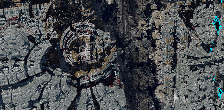
This is something I didn't have time to properly explore. You can colorize different parts of the Mandelbox by keeping track of when the fractal iteration loop escapes far enough from the origin.
My first and final experiment with colors.
The change to the distance evaluator is really small:
// Mandelbox distance function by Rrola (Buddhi's distance estimation)
// http://www.fractalforums.com/index.php?topic=2785.msg21412#msg21412

int mandelbox_material(vec3 position, int iters=7) {
    float mbox_C2 = pow(abs(SCALE), float(1-iters));
    // distance estimate
    vec4 p = vec4(position.xyz, 1.0), p0 = vec4(position.xyz, 1.0);  // p.w is knighty's DEfactor
    for (int i=0; i<iters; i++) {
        p.xyz = clamp(p.xyz, -1.0, 1.0) * 2.0 - p.xyz;  // box fold: min3, max3, mad3
        float r2 = dot(p.xyz, p.xyz);  // dp3

        // This is new! return the iteration on which the dot product above
        // crosses an arbitrary limit I set.
        if (r2 > 5.) {
            return i;
        }
        p.xyzw *= clamp(max(MR2/r2, MR2), 0.0, 1.0);  // sphere fold: div1, max1.sat, mul4
        p.xyzw = p*mbox_scalevec + p0;  // mad4
    }
    float d = (length(p.xyz) - mbox_C1) / p.w - mbox_C2;
    return 0;
}
You can run this version only when a hit has been found.
// Ray hit a surface
if (d < 1e-5) {
    // Evaluate the material and quit
    material = mandelbox_material(ro + t * rd);
    break;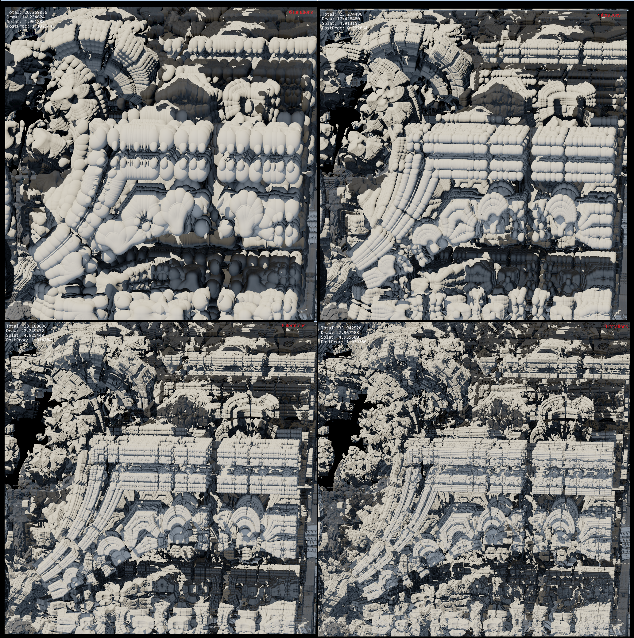
}Evaluating the Mandelbox fractal at high iteration counts can be very slow, so I used hierarchical raymarching to skip empty space. On my GTX 1060 6GB it gives a solid 10-20% speed boost at 1080p.
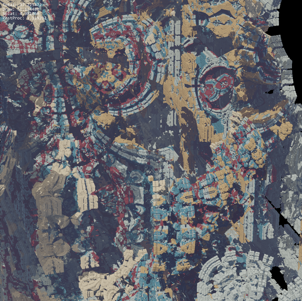
| Shot name | Image | Naive (ms) | Hierarchy (ms) | Speedup |
|---|---|---|---|---|
| Facade | 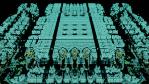 |
58 | 50 | 14% |
| Hall |  |
44 | 39 | 12 % |
| Ending | 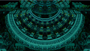 |
58 | 48 | 17 % |
The weird thing is this only minimally raises the framerate! Even though raymarching is now faster, according to my measurements, the following splatting pass gets proportionally slower. Splatting needs a lot of atomic writes so I might be hitting some bottleneck there.
Anyway, it was so difficult get this working I'm going to drop some notes below. Hopefully they will be useful to some poor soul in the future.
The raymarching technique I used was introduced in NVScene 2015 Session: GPU Unchained (Timothy Lottes) talk. Thanks to mankeli for linking me this.
The main point is that you build a conservative Z-buffer mip pyramid from top to bottom, but the bottom layers don't need to wait if parent isn't ready yet. They'll just trace the ray from t=0 in that case.
Hierarchical depth bounds. The blue boxes represent one level of the depth hierarchy. The depth image pyramid actually has levels all the way from 1x1 resolution into 1024x1024 (or 2048x2048 at 1080p) depth images.
The slides of the Lottes' talk are almost unreadable, but I managed to copy some notes from the video. I've reproduced them below.
============================================================================
                    HIERARCHICAL TRAVERSAL IN SINGLE KERNEL
============================================================================

"Reorder work to keep ALUs fully loaded,
    ok to leverage poor data access patterns if ALU bound"

THREAD TO WORK MAPPING
======================
- Not pixel to thread -> too much ALU under utilization after rays hit surf
- Rather fixed distance estimator iterations per thread

SHADER
------
 - Fetch ray
 - For fixed traversal iterations
    - Distance estimation
    - Walk forward
    - If ray hit (aka. "close enough")
        - Store result
        - Start on another ray

----------------------------------------------------------------------------
                                BREAD CRUMBS
----------------------------------------------------------------------------

  "When working in parallel, don't wait, if data isn't ready, just compute it"

TRAVERSAL ORDERING
==================
 - Order rays by parent cones first in space filling curve,

   0 -> 12 -> 4589 -> and so on
        34    67ab
              cdgh
              efij

ACCELERATION
============
 - Cones end by writing their stop depth into memory
 - Child cones will check for completed parent result,
   otherwise will start from scratch
So each level is in Z-order, and the number of nodes quadruples on each level, until we hit the native resolution. Now we need a way for a child ray to read the "bread crumbs" of its parent. So we need a child_idx -> parent_idx mapping.
How I thought about this is that we want a function tobin(i) that maps a memory offset into a mip level, and its inverse binto(b) that maps miplevel b to its starting offset in memory. The trick is that tobin(i) rounds down its result so binto(tobin(i)) returns the starting offset of a mip level the given offset i belongs to. Now the per-level Z-order index will be z = i - binto(tobin(i)).
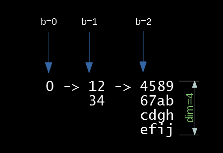
Three mip levels ("bins" in the code) with their starting memory offsets marked with blue arrows. The function tobin maps b to its starting offset.
GLSL code for these two are the following.
// Maps a ray index "i" into a bin index.
int tobin(int i)
{
    return findMSB(3*i+1)>>1;
}

// Maps a bin index into a starting ray index. Inverse of "tobin(i)."
int binto(int b)
{
    // Computes (4**b - 1) / 3
    // Could be replaced with a lookup table.
    int product = 1;
    for (int i = 0; i < b; i++)
        product *= 4;
    return (product - 1) / 3;
}
Then we'll need to convert a local Z-order index to an (x, y) coordinate we can shoot a ray through.
// Computes one coordinate of a Z-order curve
uint z2x_1(uint x)
{
    x = x & 0x55555555;
    x = (x | (x >> 1)) & 0x33333333;
    x = (x | (x >> 2)) & 0x0F0F0F0F;
    x = (x | (x >> 4)) & 0x00FF00FF;
    x = (x | (x >> 8)) & 0x0000FFFF;
    return x;
}

// Maps 32-bit Z-order index into 16-bit (x, y)
uvec2 z2xy(uint z)
{
    return uvec2(z2x_1(z), z2x_1(z>>1));
}
Finally, putting it all together:
// Maps a ray index "i" into UV coordinates that can be used for raymarching.
vec2 i2ray(int i, out ivec2 squareCoord, out int parentIdx, out int sideLength)
{
    int b = tobin(i);
    int start = binto(b);
    int z = i - start;
    uvec2 coord = z2xy(uint(z));
    int idim = 1 << b;
    int size = idim * idim;
    float dim = float(idim);

    int parent_size = size / 4;
    int parent = int(start - parent_size) + (z/4);

    squareCoord = ivec2(coord + vec2(.5));
    parentIdx = parent;
    sideLength = idim;

    vec2 uv = vec2(0.5/dim) + coord / vec2(dim);

     return uv;
}
I understand this wasn't well explained, but I wanted to put the details here for reference.
The Z-hierarchy above only works in power-of-two resolutions. We need to round up the actual resolution up but this causes a lot of waste.
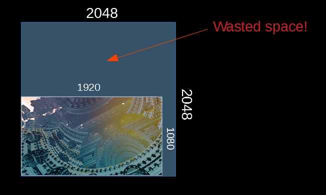
Wasted space in the Z-buffer hierarchy.
The memory use is not a problem, but we definitely don't want to launch threads on the GPU that would not produce useful results. The way I solved this was to precompute an array of valid ray indices whose UV coordinates overlap with the real viewport, and map each GPU thread index to the precomputed ray index.
At the beginning of the raymarch shader we then do a little dance:
// Fetch the index for this thread
int arrayIdx = atomicAdd(nextRayIndex, 1);

// This thread has no work so quit
if (arrayIdx >= rayIndexBufferMaxElements)
    return;

// Map the thread index into a ray index
// This uses static lookup table precomputed on the CPU
int myIdx = rayIndices[arrayIdx];

// Map the ray index into UV
vec2 squareUV = i2ray(myIdx, squareCoord, parentIdx, sideLength);
squareUV /= screenBoundary.xx;
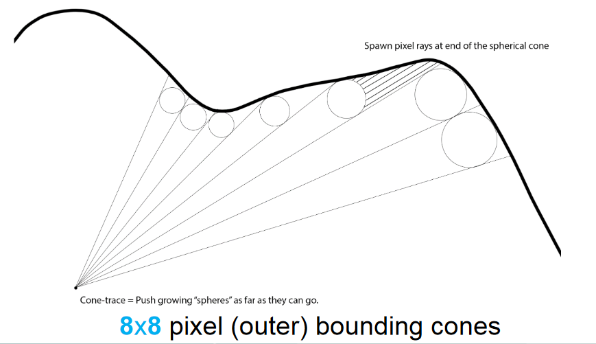
// Raymarch with squareUVThe basic idea is to march the depth buffer rays until ray cone becomes larger than the distance to a surface. Then you store t, the distance travelled. But what is it, exactly?
In Seven/Fulcrum's talk from 2012, Rendering Mandelbox fractals faster with Cone Marching (slides), it is said that the depth marching rays should store their earlier "safe" tn − 1 instead of the last distance tn. In the end I just couldn't get this working right: children would sometimes terminate before their parents.
Lottes' talk wasn't any help either since the notes tell to terminate the raywhen "close enough."
Finally things started working (99% of the time) when I eyeballed GPU-based clay simulation and ray-tracing tech in Claybook by Sebastian Aaltonen. The interesting slides are 26—28. I've copied the relevant parts below.
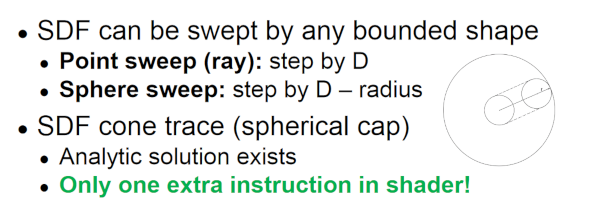
SDF Sweeps, slide 26
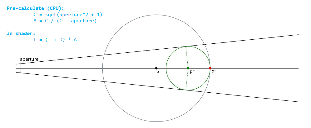
Cone-Tracing Analytic Solution, slide 27
Coarse Cone-Trace Pre-Pass, slide 28
So instead of storing t in the raymarching loop, I stored tn − 1 + dn − 1 − cn − 1, where d is the distance to a closest surface, and c is the cone size. This is not really correct since it equates to a sphere sweep from the penultimate step to the last one, but it works almost perfectly.
If you know how this should be done I'm all ears!
The raymarching loop is then the following.
float t = start_t;
float last_t = t;

for (i = 0; i < num_iters; i++) {
    float d = scene(ro + t * rd);
    float coneWorldRadius = PIXEL_RADIUS * (t+PROJECTION_PLANE_DIST) / PROJECTION_PLANE_DIST;

    if (d <= coneWorldRadius) {
        // In depth rays we write the earlier, "safe", z value to the buffer.
        t = last_t;
        break;
    }

    // Actually a sphere sweep step instead of a cone or a ray.
    last_t = (t + d) - coneWorldRadius;

    t = (t + d) * STEP_FACTOR; // Aaltonen's slide 27 above

    if (t >= end_t) {
        break;
    }
}
I tried some approaches that didn't work at all, or were poorly implemented by me because, well, this is still democoding in a hurry.
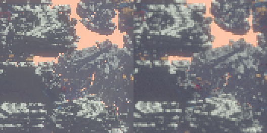
Originally I wanted to apply the 2x2 reconstruction filter only at Z-buffer boundaries to quickly blur fractal silhouettes. This caused visible flickering because the 1 spp Z-buffer is pretty noisy. In the end I applied the reconstruction filter to the whole screen avoiding the edge detection issue altogether. Then I ran to the next problem.
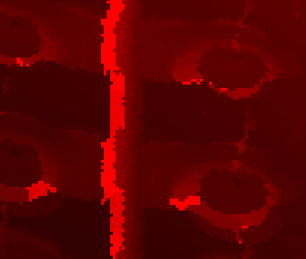
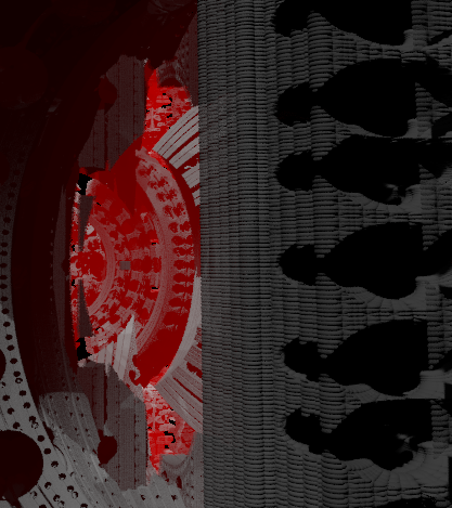
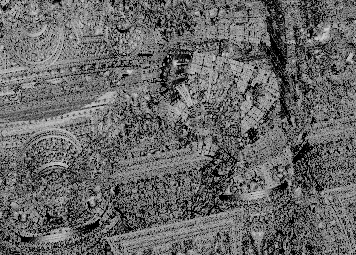
A noisy Z-buffer with only one jittered ray per pixel.
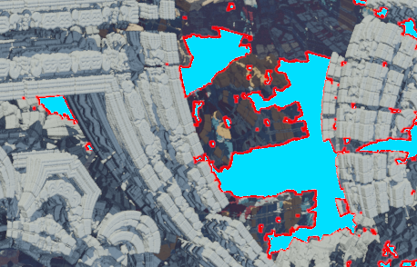
Z-buffer boundaries colored in red.
The AA looks fine in static images. Left: All with 1x1 box filter (basically no filter), right: with 2x2 edge reconstruction filter.
I didn't impelement weighted OIT properly since it requires you to keep track of both (a) a sum of weights, and (b) product of 1-alpha values per-pixel. I only had a sum of alphas to use, so it broke down on faraway objects. That's why you see aliasing in the first shot of the demo.
Because of fixed-point range issues, I had to tone down the increased weight of points close to camera. This causes "ghosting" and far away points to stick through closer geometry.
Some objects become transparent with fast moving cameras if Z-weighting is not steep enough.
The way you should do it in unsigned fixed point is to store a sum of biased logarithms (you need a bias because they can get negative) and N the number of values in the sum. This way you can arrive at the real product of alphas by subracting the correct bias. So in the point splatting shader:
# take log of 1 - alpha and bias it into [0..100] range
# before adding it to the accumulator
sum_of_logs += uint(int(max(-2, log(1.0 - alpha)) * 50) + 100)
N += 1
In the resolve shader:
# subtract the bias before inverting the logs with an exponential
product_of_alphas = exp((sum_of_logs - N*100)/50.)
Now you can use product_of_alphas to compute proper approximate coverage using McMorgan's weighted OIT equation (6) (see above).
Take this advice witha grain of salt since I haven't tried actually tried this :)
I tried to use regular TAA techniques but they break down on high-contrast, high-frequency details. I believe the main culprit is the history clamping step which causes visible flickering.
TAA neighbor color clamp causes some history buffer colors be rejected at sharp contrast boundaries

Same as above.
The other issue with TAA is that you need a good filter to avoid excessive blurring of the history buffer. Even if you use a good filter, the constant weight people usually use in expontential history decay makes it possible to exploit only ~11 frames at most. See this graph from A Survey of Temporal Antialiasing Techniques by L. Yang, S. Liu, and M. Salvi.
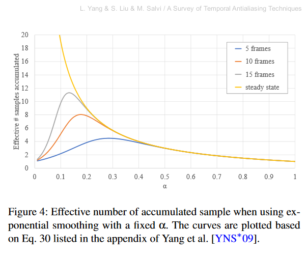
Effective number of samples as a function of history weight α. As you can see it peaks at α ≈ 0.12 where you get ~11 effective history samples.
This means the approach I used with roughly 10 samples per pixel has pretty much the same amount of history information you'd get with a tweaked TAA with a fixed alpha. You could use fixed number of history frames (like 4 frames, see Towards Cinematic Quality, Antialiasing in 'Quantum Break'), but the other problems with TAA remain. Finally, it's not as easy to sample the future as with point clouds.
Geometric aliasing is hidden by the super sampling in diffuse materials, but it's still not enough for shiny surfaces. The way to solve this is to accumulate normals in screenspace and do deferred shading with roughness = length(accumulatedNormal). See Toksvig's classic Mipmapping Normal Maps and Brian Karis' thoughts on von Mises-Fisher lobes.
Extreme geometric aliasing with a 1x1 box filter in the detailed fractal makes bright speculars very ugly.
Adding shadows, a proper reconstruction filter, and toning down the specular exponent helps but in motion it still flickers way too much.
Point splatting accumulation could've been done in a non-correlated color space with 32-bits per pixel. I tried to use 12-bit luminance and 10 bits for both chrominances axes, but it's annoying in unsigned fixed point. See chapter 7 in The Compact YCoCg Frame Buffer by P. Mavridis and G. Papaioannou for discussion of blending. They also do chroma subsampling which I didn't need.
Even though you can dither colors to hide even huge quantization, the problem here was the OIT that blows up color magnitudes of points with small Z coordintes. So I had to resort to 64-bit accumulator per pixel. It looks very ugly when the accumulators overflow.
Eternal Fortress is a tech demo and making it was a great learning experience for me. I'd like to thank msqrt, noby, mankeli, Rimina, and Juho for technical discussions, and most of all for encouraging me when the whole project seemed like a failure.
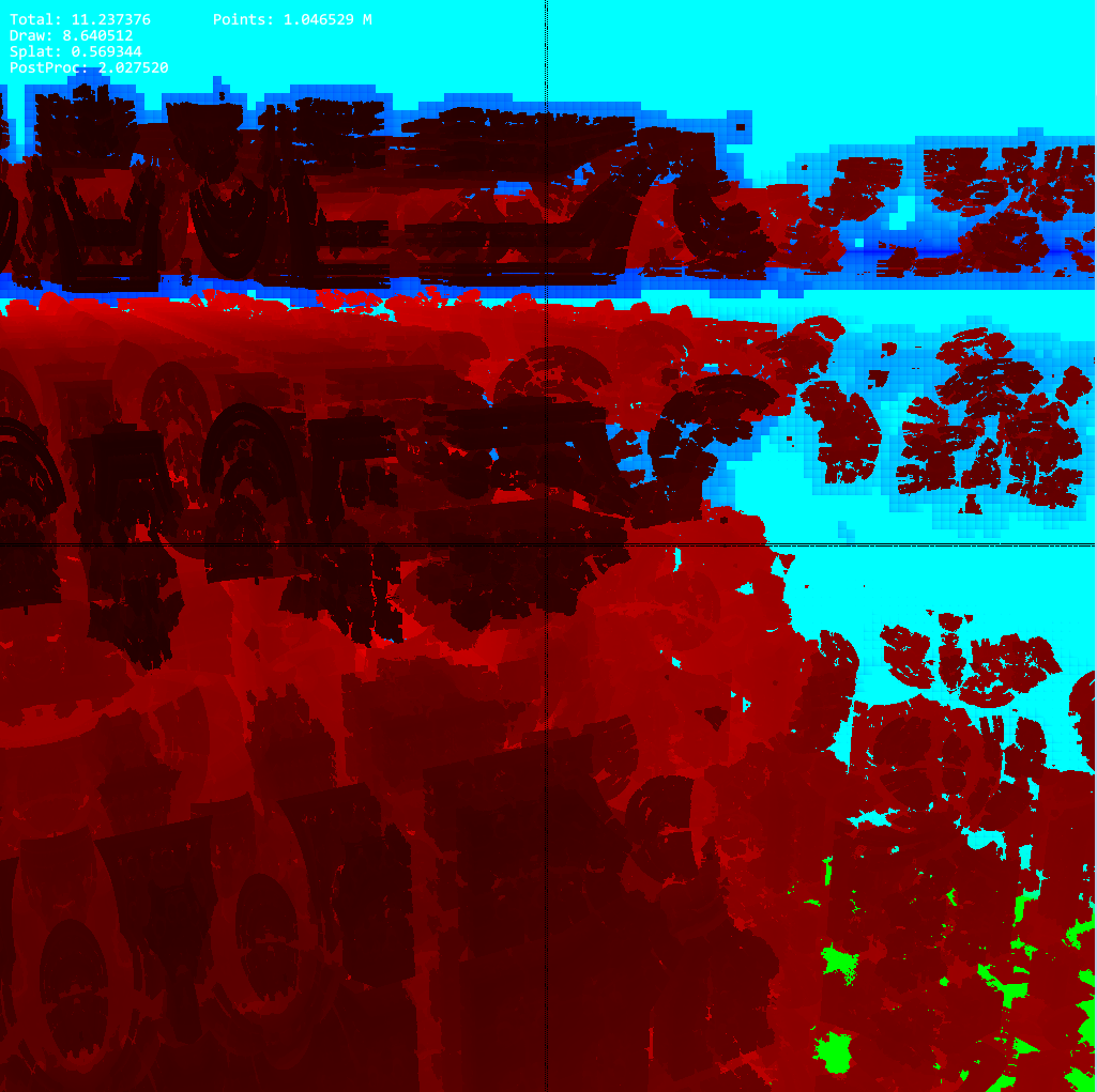
Hierarchical raymarcher glitching when child rays didn't add the parent t into their progress.